Table of Contents
- Introduction
- Assemble the Parts
- Configure the Radio
- Wire up the Circuit
- Use it!
1) Introduction
Let's get physical! Join this joystick to your XBee radio for a terrific way to add movement to your project, sending all kinds of things in different directions.
Achieve full wireless control of household robots, industrial equipment, safety cameras...even stratosphere-seeking weather balloons. Set about inventing a new class of cat toys or create a new way to interact with museum exhibits. Maybe you'd like to make an interactive lawn sprinkler that waters your name in the grass? Here's a terrific way to control it! This tutorial walks you through the easy way to connect a joystick to your XBee. Create a wonderful wireless controller and drive your dreams!
2) Assemble the Parts
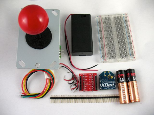
To hook up a joystick to an XBee, you'll need:
4) Wire up the Circuit
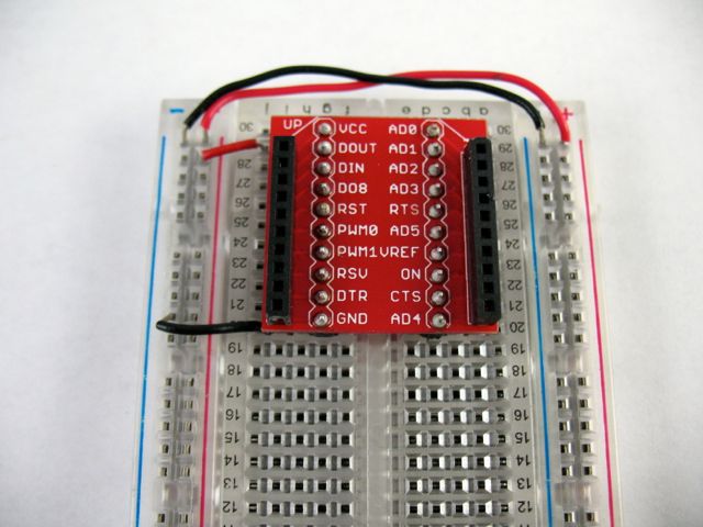
- Place the XBee adapter into the breadboard and wire up the power buses to each other. Next, connect the VCC terminal of the XBee adapter to the positive rail and the ground terminal to the negative rail.
- The joystick is really a set of four switches that all share a common ground. To make it easier to connect them to a breadboard, you can solder male header pins onto each. We kept the common wire (typically the black one) separate so that it could be connected directly to the negative power rail.
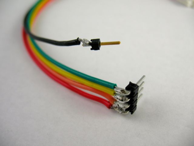
- Connect the common wire to the ground power rail. Connect the remaining joystick switch wires to XBee input pins D0, D1, D2 and D3 (physical pins 20, 19, 18 and 17 on the right-hand side of the XBee).
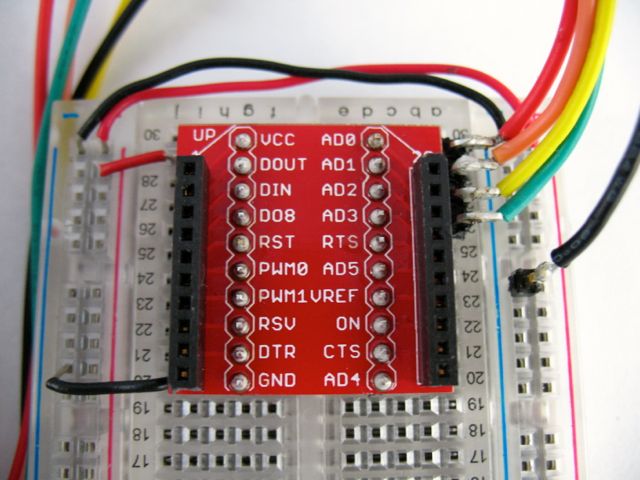
- We made it easier to attach the battery holder to the breadboard by soldering some male headers onto its positive and negative wiring leads.
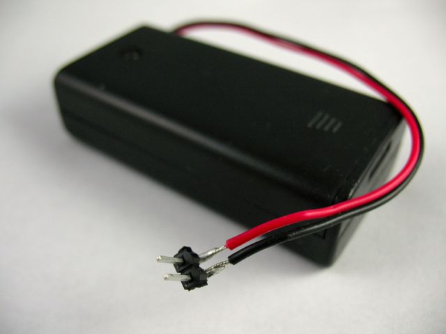
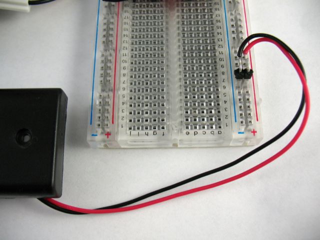
- Connect the battery pack directly to the ground and power rails.
- Insert your configured XBee into the breadboard adapter and your XBee Joystick is all done!
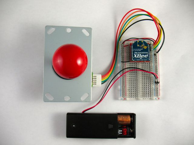
- Below is a breadboard layout of the circuit along with a schematic.
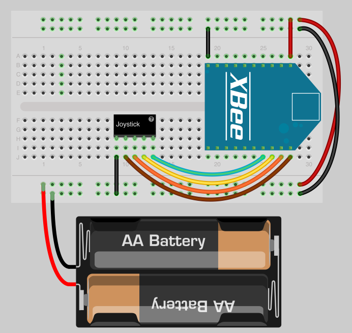
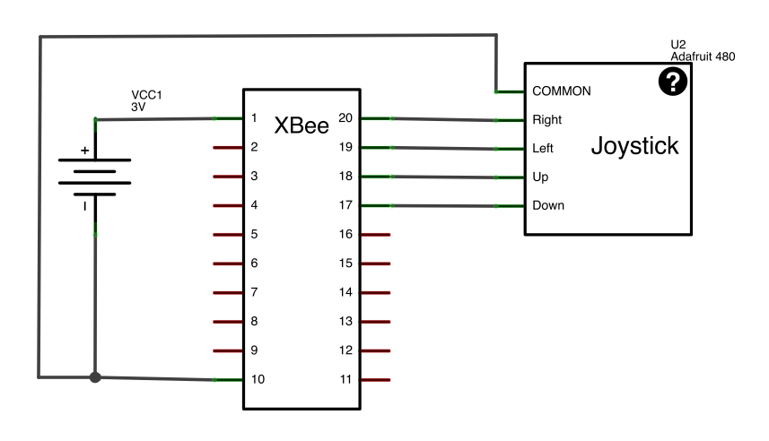
Note: Your joystick output wiring arrangement might be different, so always check the operation to confirm before finalizing your project.
5) Use it!
Now that you know how to connect a joystick to an XBee radio, take a look at our output tutorials for ideas on where to send the signals. The video above shows the joystick connected to a group of four wireless LEDs. You might want to try controlling stepper motors to create directional movement, orchestrating water pumps into a casino-style fountain or harvesting crops from the comfort of your porch swing. Every which way is a joy!