Projects built with Digi XBee® 3 Cellular modules can be anything from
agricultural applications to
drones,
green tech and industrial projects such as
smart HVAC motors. The choices product developers must make and the challenges they face depend upon on the complexity of the design, the intended use case, the distance from cell towers and other key considerations.
This means that along the way, there are myriad decisions to make with regard to module selection, platform design, communications protocols, antennas, and certifications, just to name a few.
The final step is production. Once your product is ready for manufacturing, there are typically three things remaining to test:
- Do the XBee 3 module and the cellular modem on the XBee 3 module have the correct firmware?
- Is the XBee 3 module placed on the PCB correctly?
- Are any external antennas attached correctly?
The
Digi Wireless Design Services team provides the following advice on how to perform successful tests. Many of these solutions also apply to other non-cellular XBee and XBee 3 modules.
Firmware Verification and Configuration
While all XBee modules are factory programmed, controlling exactly what firmware is on the modules is often desirable. Modules purchased from Digi distributors may require firmware updates to match the most recent Digi firmware release. Similarly, production requirements may require that the firmware is actually backdated in order to meet product specifications.
Digi XBee modules provide several different programming options for both on-board and off-board programming.
Off-Board Programming
The easiest, fastest and most robust method for programming and configuring XBee modules is the
Digi XBee Multi Programmer (XBMP). The XBMP can program and configure XBees that mount to boards using through-hole, SMT or MMT connections. A single XBMP can program and configure up to 6 XBees and additional XBMPs can be daisy-chained together to scale to your manufacturing needs. Programming and configuration profiles are easily created using the same
Digi XCTU® Configuration Platform that many developers will already be familiar with.
A single XBee module can also be updated using a
Digi XBIB-C Development Board and the XCTU application. This option would not likely not be suitable for large scale production but can be an excellent solution for prototype and early pilot production.
On-Board Programming
Once XBees are placed onto PCB assembly (PCBA), there are several options for programming and configuration. Choosing the best method will depend on your manufacturing environment, board design, and what interfaces to the XBee module are available. For example, on designs that expose the serial interface to the XBee module and a separate interface to the cellular radio, the actual time to program and configure
a single XBee module is comparable to speeds obtained when using the XBMP. It may also be possible to use Digi XCTU to minimize the efforts needed to create an automated manufacturing process.
Exposing the XBee programming interfaces for production boards does add costs to the product’s bill of materials. Costs can be reduced by not populating the programming connectors and instead using a probe fixture to make contact with test-points or unpopulated connector pad. A good compromise between ease-of-use and cost for some connectors is to probe the populated connector and then simply swap probes (no-tools required typically) to accommodate probing of the part.
Lastly, on designs that do not expose the physical programming interfaces but that utilize a microcontroller or other host processor to talk to the XBee module, programming and configuration is typically done through code running on the host controller or code running on a PC that is sent to the host controller over a debug console interface.
Manufacturing Test Processes
Multiple tests take place the manufacturing process. We will cover two additional testing processes in the manufacturing cycle.
Placement Testing
Regardless of how the XBee is programmed and configured, a basic functional test of the XBee module is required in most manufacturing processes after the XBee is placed on a board. For designs where a communications interface to the XBee is exposed either directly or via a debug console interface to the host controller, a simple verification of the XBee firmware version, cellular radio version and at least one custom configuration value — typically the cellular APN — may be sufficient. Product deployments that require per-product cellular data to be recorded (e.g., cellular modem IMEI number and SIM card ICCID number) will do so at this time as well.
Radio and Antenna Testing
Since both the XBee module and the external antenna are pre-tested, the chance of these components failing is low. The highest risk for failure in manufacturing, therefore, is connection of any antennas to the XBee module.
In manufacturing, avoiding the use of an actual cellular tower connection is often desirable due to the variability in signal strength and the time it takes to connect to a live network. Offshore manufacturing presents even larger challenges since the network may not even be available.
Use of a spectrum analyzer (SA) that can receive signaling from an antenna inside a small isolation box is reliable and deterministic way to verify antenna connection and placement. A test antenna, mounted inside the isolation box and directly connected to the SA, receives signals from the device under test (DUT) antenna connected to the XBee. The DUT is placed in a frame mounted inside the RF box that ensures the orientation of the device is consistent from test to test.
The XBee cellular radio is placed into a constant transmit mode and the transmit power and frequency of the XBee cellular radio is measured. The measurements from this type of test ensure that the antenna connected and properly placed, which at the manufacturing level is our primary concern.
A simple LabView test panel, which many SA manufacturers will provide to you at no cost, can be used to configure the SA and record the measurements. Here is what the output of the SA looks like on a test similar to the one described above.
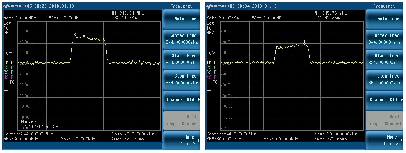
These are measurements from an antenna connected to a Digi XBee CAT1 cellular module transmitting over-the-air to an antenna inside an RF isolated box. The image on the left is a good signal with excellent separation between the in-band maximum power and the noise floor. The image on the right shows how a signal is still present but is attenuated by over 8 dB. The attenuated image is the result of simply moving the device inside the RF chamber 90 degrees.
A signal without an antenna connection would show even more attenuation than what we see above and may not be capable of even connecting to a cellular network. The attenuated signal shown above, however, would very likely connect and shows how a simple ping test to a live cellular tower may not catch issues where the antenna is not properly placed.
In designs that require testing of not only signal strength but signal quality, a cell site simulator can be used in place of an SA, but costs of such equipment is often prohibitive.
Digi Wireless Design Services: We are Here for You
There are many different ways to program, configure and test Digi XBee modules in manufacturing with many trade-offs in terms of test system costs, reliability, repeatability, and overall test time.
Digi Wireless Design Services can provide services at many level, tailored to your needs. From small consultation services to get you started on your product production or full turn-key manufacturing test solutions, Digi WDS is here to help.