LED Example: XBee Wi-Fi

Table of Contents

  1. Introduction
  2. Assemble the Parts
  3. Configure the Radio
  4. Wire up the Circuit
  5. View it!
  6. Use it!


1) Introduction

Making an LED illuminate is one of the first things many people do when they start learning electronics. It's also often the most satisfying. We’re putting a wireless spin on that achievement by hooking up an LED to an XBee’s output, then controlling it from the web.

Let's get blinking!

2) Assemble the Parts

XBee_wi-fi_kit3xbee-wifi-led-widget-parts


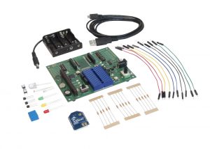
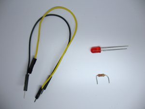
To hook up an LED sensor you'll need:

*...or a powered XBee Wi-Fi with breadboard and jumper wires.

3) Configure the Radio

You'll configure the radio using your free Device Cloud account. (Note that radios can also be configured using XCTU.)

NOTE: If your radio was recently configured by the XBee Wi-Fi Cloud Kit then the sampling rate and pin settings are already set. You can safely skip these steps.

  • Log in to Device Cloud.
  • Select Devices under the Device Management tab.
    DC-devices-list
  • Select the XBee Wi-Fi that you are configuring, then select Properties or double-click to open the Properties window for that device.
  • Select Configurations, then Input and Output Settings, then confirm that DIO4/SPI_MOSI is set to Output Low.
    xbee-wifi-led-io-setting
  • On the same page, confirm that Sample Rate is set to 5000 ms which will take a sample every five seconds.
  • Save your changes!

4) Wire up the Circuit

You will build this sensor circuit using the XBee Development Board.

  • Plug the 270 ohm resistor into the breadboard as shown. It will limit the current flowing to the LED.
    • Connect one end of a yellow (or any other color) jumper wire to the same breadboard row as one end of this resistor. Connect the other end of this wire to the XBee's DIO4 pin.
  • Plug in the LED so that its long leg (+) connects to the same junction row as the open leg of the resistor. The shorter leg (-) goes into another unused row. (Note: an LED has polarity, meaning that its orientation matters! If you put it into this circuit backwards it will not light up.)
    • Connect a black jumper wire from the short leg of the LED to ground (GND) as shown.
      xbee-wifi-led-widget-board-cu
  • Set the DIP switch for DIO4 on the PCB to OFF to disconnect the soldered-on component.
    xbee-wifi-led-widget-switch
  • Here's what everything should look like:
    xbee-wifi-led-breadboard xbee-wifi-led-circuit xbee-wifi-led-widget-board

5) View It!

You will use the XBee Wi-Fi Cloud Kit's web application to configure a widget for viewing the light readings from your sensor.

  • Log in to the XBee Wi-Fi Cloud Kit web application
    cloudkit-login
  • Use the Add Widget button to create a new display widget
    add-widget
  • Choose On/Off Switch Widget for the widget type.
  • Add a label such as "LED"
  • Choose your XBee Wi-Fi device by its ID.
  • Select DIO4 as the input stream and check the device configuration to make sure it is configured properly.
  • Make sure the Invert Values checkbox is unchecked because in this circuit ON maps normally to high output.
  • Make sure that Read Only also remains unchecked. We're going to use this switch as an input from the web.
    xbee-wifi-led-widget-settings
  • Save the changes to see your new Widget:
    xbee-wifi-led-widget-fullscreen

6) Use it!

xbee-wifi-led-widget

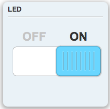
Get ready to shed some light with your new LED! Click on the switch widget to turn the LED on. The switch will wait for Device Cloud to hear back from the XBee Wi-Fi that its output state has changed, and then become available again. Click the switch again to douse the light. You just made a physical output that you can operate from the next room,  across town or across an ocean!

If you like LEDs there are many out there to try. Also, this simple circuit is the starting point for controlling everything from motors to monkeys. To turn on and off something that runs on a higher current, try making a relay circuit.

Tags: Wi-Fi XBee